
Mass Analyzers (Mass Spectrometry)
- Page ID
- 324
Mass spectrometry is an analytic method that employs ionization and mass analysis of compounds to determine the mass, formula and structure of the compound being analyzed. A mass analyzer is the component of the mass spectrometer that takes ionized masses and separates them based on charge to mass ratios and outputs them to the detector where they are detected and later converted to a digital output.
Introduction
There are six general types of mass analyzers that can be used for the separation of ions in a mass spectrometry.
- Quadrupole Mass Analyzer
- Time of Flight Mass Analyzer
- Magnetic Sector Mass Analyzer
- Electrostatic Sector Mass Analyzer
- Quadrupole Ion Trap Mass Analyzers
- Ion Cyclotron Resonance
Quadrupole Mass Analyzer
The DC bias will cause all the charged molecules to accelerate and move away from the center line, the rate being proportional to their charge to mass ratio. If their course goes off too far they will hit the metal rods or the sides of the container and be absorbed. So the DC bias acts like the magnetic field B of the mass spec and can be tuned to specific charge to mass ratios hitting the detector.

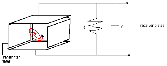
The two sinusoidal electric fields at 90 orientation and 90 degrees degrees phase shift will cause an electric field which oscillates as a circle over time. So as the charged particles fly down toward the detector, they will be traveling in a spiral, the diameter of the spiral being determined by the charge to mass ratio of the molecule and the frequency and strength of the electric field. The combination of the DC bias and the circularly rotating electric field will be the charge particles will travel in a spiral which is curved. So by timing the peak of the curved spiral to coincide with the position of the detector at the end of the quadrupole, a great deal of selectivity to molecules charge to mass ratio can be obtained.
TOF (Time of Flight) Mass Analyzer
TOF Analyzers separate ions by time without the use of an electric or magnetic field. In a crude sense, TOF is similar to chromatography, except there is no stationary/ mobile phase, instead the separation is based on the kinetic energy and velocity of the ions.
.bmp?revision=1)
Ions of the same charges have equal kinetic energies; kinetic energy of the ion in the flight tube is equal to the kinetic energy of the ion as it leaves the ion source:
\[KE = \dfrac{mv^2}{2} = zV \label{1}\]
The time of flight, or time it takes for the ion to travel the length of the flight tube is:
\[T_f = \dfrac{L}{v} \label{2}\]
- with \(L\) is the length of tube and
- \(v\) is the velocity of the ion
Substituting Equation 1 for kinetic energy in Equation 2 for time of flight:
\[T_f = L\sqrt{\dfrac{m}{z}}\sqrt{ \dfrac{1}{2 V}} \propto \sqrt{\dfrac{m}{z}} \label{3}\]
During the analysis, \(L\), length of tube, the Voltage from the ion source \(V\) are held constant, which can be used to say that time of flight is directly proportional to the root of the mass to charge ratio.
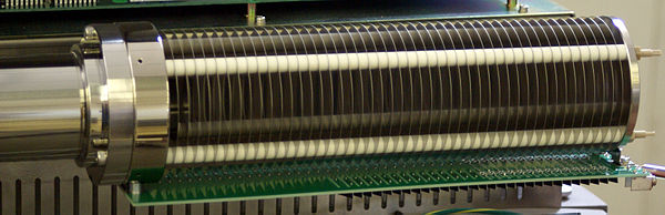
Unfortunately, at higher masses, resolution is difficult because flight time is longer. Also at high masses, not all of the ions of the same m/z values reach their ideal TOF velocities. To fix this problem, often a reflectron is added to the analyzer. The reflectron consists of a series of ring electrodes of very high voltage placed at the end of the flight tube. When an ion travels into the reflectron, it is reflected in the opposite direction due to the high voltage. The reflectron increases resolution by narrowing the broadband range of flight times for a single m/z value. Faster ions travel further into the reflectrons, and slower ions travel less into the reflector. This way both slow and fast ions, of the same m/z value, reach the detector at the same time rather then at different times, narrowing the bandwidth for the output signal.
Magnetic Sector Mass Analyzer
Similar to time of flight (TOF) analyzer mentioned earlier,in magnetic sector analyzers ions are accelerated through a flight tube, where the ions are separated by charge to mass ratios. The difference between magnetic sector and TOF is that a magnetic field is used to separate the ions. As moving charges enter a magnetic field, the charge is deflected to a circular motion of a unique radius in a direction perpendicular to the applied magnetic field. Ions in the magnetic field experience two equal forces; force due to the magnetic field and centripetal force.
\[F_B= zvB =F_c= \dfrac{mv^2}{r} \label{4}\]
The above equation can then be rearranged to give:
\[v = \dfrac{Bzr}{m} \label{5}\]
If this equation is substituted into the kinetic energy equation:
\[KE= zV=\dfrac{mv^2}{2} \label{6}\]
\[\dfrac{m}{z}=\dfrac{B^2r^2}{2V} \label{7}\]
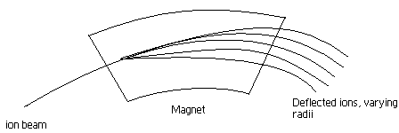
Basically the ions of a certain \(m/z\) value will have a unique path radius which can be determined if both magnetic field magnitude \(B\), and voltage difference \(V\) for region of acceleration are held constant. when similar ions pass through the magnetic field, they all will be deflected to the same degree and will all follow the same trajectory path. Those ions which are not selected by \(V\) and \(B\) values, will collide with either side of the flight tube wall or will not pass through the slit to the detector. Magnetic sector analyzers are used for mass focusing, they focus angular dispersions.
Electrostatic Sector Mass Analyzer
Is similar to time of flight analyzer in that it separates the ions while in flight, but it separates using an electric field. Electrostatic sector analyzer consists of two curved plates of equal and opposite potential. As the ion travels through the electric field, it is deflected and the force on the ion due to the electric field is equal to the centripetal force on the ion. Here the ions of the same kinetic energy are focused, and ions of different kinetic energies are dispersed.
\[KE = zV =\dfrac{mv^2}{2} \label{8}\]
\[F_E= zE= F_c=\dfrac{mv^2}{R} \label{9}\]
Electrostatic sector analyzers are energy focusers, where an ion beam is focused for energy. Electrostatic and magnetic sector analyzers when employed individually are single focusing instruments. However when both techniques are used together, it is called a double focusing instrument., because in this instrument both the energies and the angular dispersions are focused.
Quadrupole Ion Trap Mass Analyzers
This analyzer employs similar principles as the quadrupole analyzer mentioned above, it uses an electric field for the separation of the ions by mass to charge ratios. The analyzer is made with a ring electrode of a specific voltage and grounded end cap electrodes. The ions enter the area between the electrodes through one of the end caps. After entry, the electric field in the cavity due to the electrodes causes the ions of certain m/z values to orbit in the space. As the radio frequency voltage increases, heavier mass ion orbits become more stabilized and the light mass ions become less stabilized, causing them to collide with the wall, and eliminating the possibility of traveling to and being detected by the detector.

The quadrupole ion trap usually runs a mass selective ejection, where selectively it ejects the trapped ions in order of in creasing mass by gradually increasing the applied radio frequency voltage.
Ion Cyclotron Resonance (ICR)
ICR is an ion trap that uses a magnetic field in order to trap ions into an orbit inside of it. In this analyzer there is no separation that occurs rather all the ions of a particular range are trapped inside, and an applied external electric field helps to generate a signal. As mentioned earlier, when a moving charge enters a magnetic field, it experiences a centripetal force making the ion orbit. Again the force on the ion due to the magnetic field is equal to the centripetal force on the ion.
\[zvB=\dfrac{mv^2}{r} \label{10}\]
Angular velocity of the ion perpendicular to the magnetic field can be substituted here \(w_c=v/r\)
\[zB=mw_c \label{11}\]
\[w_c=\dfrac{zB}{m} \label{12}\]
Frequency of the orbit depends on the charge and mass of the ions, not the velocity. If the magnetic field is held constant, the charge to mass ratio of each ion can be determined by measuring the angular velocity \(\omega_c\). The relationship is that, at high \(w_c\), there is low m/z value, and at low \(\omega_c\), there is a high m/z value. Charges of opposite signs have the same angular velocity, the only difference is that they orbit in the opposite direction.
To generate an electric signal from the trapped ions, a vary electric field is applied to the ion trap
\[E=E_o \cos{(\omega_c t)} \label{13}\]
When the \(\omega_c\) in the electric field matches the \(\omega_c\) of a certain ion, the ion absorbs energy making the velocity and orbiting radius of the ion increase. In this high energy orbit, as the ion oscillates between two plates, electrons accumulate at one of the plates over the other inducing an oscillating current, or current image. The current is directly proportional to the number of ions in the cell at a certain frequency.
In a Fourier Transform ICR, all of the ions within the cell are excited simultaneously so that the current image is coupled with the image of all of the individual ion frequencies. A Fourier transform is used to differential the summed signals to produce the desired results.
References
- K. Downard, Mass Spectrometry: A Foundation Course, The Royal Society of Chemistry: UK 2004, Chapter 3
- Skoog, Holler, Grouch, Principles of Instrumental Analysis, Thomson Brooks/Cole 2007, chapter 20
- C. Herbert, R. Johnstone, Mass Spectrometry Basics, CRC Press LLC, 2003 chapter 25, 26, 39
- E. De Hoffman, V. Stroobant, Mass Spectrometry: Principles and Applications, 2nd ed.;Wiley: England, 2001, chapter 2
Contributors and Attributions
- Ommaima Khan