
Powder X-ray Diffraction
- Page ID
- 314
When an X-ray is shined on a crystal, it diffracts in a pattern characteristic of the structure. In powder X-ray diffraction, the diffraction pattern is obtained from a powder of the material, rather than an individual crystal. Powder diffraction is often easier and more convenient than single crystal diffraction since it does not require individual crystals be made. Powder X-ray diffraction (XRD) also obtains a diffraction pattern for the bulk material of a crystalline solid, rather than of a single crystal, which doesn't necessarily represent the overall material. A diffraction pattern plots intensity against the angle of the detector, \(2\theta\).
Introduction
Since most materials have unique diffraction patterns, compounds can be identified by using a database of diffraction patterns. The purity of a sample can also be determined from its diffraction pattern, as well as the composition of any impurities present. A diffraction pattern can also be used to determine and refine the lattice parameters of a crystal structure. A theoretical structure can also be refined using a method known as Rietveld refinement. The particle size of the powder can also be determined by using the Scherrer formula, which relates the particle size to the peak width. The Scherrer fomula is
\[t = \dfrac{0.9 \lambda}{\sqrt{B^2_M-B^2_s} \cos \theta} \nonumber \]
with
- \(\lambda\) is the x-ray wavelength,
- \(B_M\) is the observed peak width,
- \(B_S\) is the peak width of a crystalline standard, and
- \(\theta\) is the angle of diffraction.
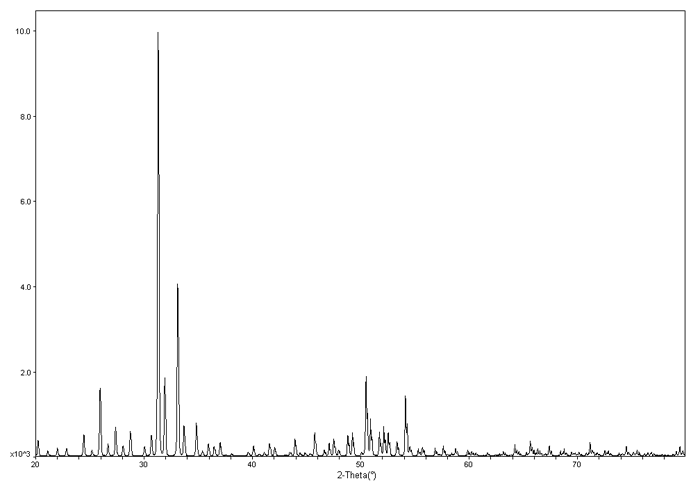
To the left is an example XRD pattern for \(Ba_{24}Ge_{100}\). The x axis is \(2\theta\) and the y axis is the intensity.
Bragg's Law
X-rays are partially scattered by atoms when they strike the surface of a crystal. The part of the X-ray that is not scattered passes through to the next layer of atoms, where again part of the X-ray is scattered and part passes through to the next layer. This causes an overall diffraction pattern, similar to how a grating diffracts a beam of light. In order for an X-ray to diffract the sample must be crystalline and the spacing between atom layers must be close to the radiation wavelength.
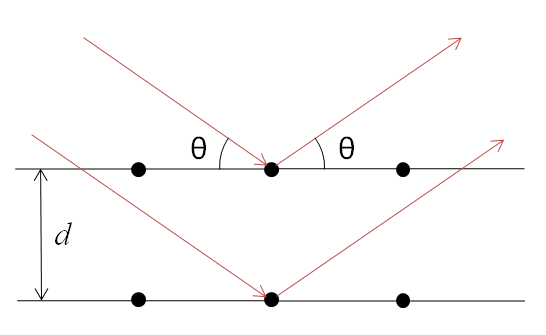
If beams diffracted by two different layers are in phase, constructive interference occurs and the diffraction pattern shows a peak, however if they are out of phase, destructive interference occurs appear and there is no peak. Diffraction peaks only occur if
\[\sin \theta = \dfrac{n\lambda}{2d} \nonumber \]
where
- \(\theta\) is the angle of incidence of the X-ray,
- \(n\) is an integer,
- \(\lambda\) is the wavelength, and
- \(d\) is the spacing between atom layers.
Since a highly regular structure is needed for diffraction to occur, only crystalline solids will diffract; amorphous materials will not show up in a diffraction pattern.
Instrumentation
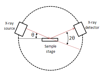
A powder X-ray diffractometer consists of an X-ray source (usually an X-ray tube), a sample stage, a detector and a way to vary angle θ. The X-ray is focused on the sample at some angle θ, while the detector opposite the source reads the intensity of the X-ray it receives at 2θ away from the source path. The incident angle is than increased over time while the detector angle always remains 2θ above the source path.
X-ray Tubes
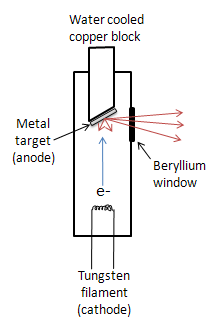 While other sources such as radioisotopes and secondary fluorescence exist, the most common source of X-rays is an X-ray tube. The tube is evacuated and contains a copper block with a metal target anode, and a tungsten filament cathode with a high voltage between them. The filament is heated by a separate circuit, and the large potential difference between the cathode and anode fires electrons at the metal target. The accelerated electrons knock core electrons out of the metal, and electrons in the outer orbitals drop down to fill the vacancies, emitting X-rays. The X-rays exit the tube through a beryllium window. Due to massive amounts of heat being produced in this process, the copper block must usually be water cooled
X-ray Detectors
While older machines used film as a detector, most modern equipment uses transducers that produce an electrical signal when exposed to radiation. These detectors are often used as photon counters, so intensities are determined by the number of counts in a certain amount of time.
Gas-Filled Transducers
A gas-filled transducer consists of a metal chamber filled with an inert gas, with the walls of the chamber as a cathode and a long anode in the center of the chamber. As an X-ray enters the chamber, its energy ionizes many molecules of the gas. The free electrons then migrate towards the anode and the cations towards the cathode, with some recombining before they reach the electrodes. The electrons that reach the anode cause current to flow, which can be detected. The sensitivity and dead time (when the transducer will not respond to radiation) both depend on the voltage the transducer is operated at. At high voltage, the transducer will be very sensitive but have a long dead time, and at low voltage the transducer will have a short dead time but low sensitivity.
Scintillation Counters
In a scintillation counter, a phosphor is placed in front of a photomultiplier tube. When X-rays strike the phosphor, it produces flashes of light, which are detected by the photomultiplier tube.
Semiconductor Transducers
A semiconductor transducer has a gold coated p-type semiconductor layered on a lithium containing semiconductor intrinsic zone, followed by an n-type semiconductor on the other side of the intrinsic zone. The semiconductor is usually composed of silicon; germanium is used if the radiation wavelength is very short. The n-type semiconductor is coated by an aluminum contact, which is connected to a preamplifier. The entire crystal has a voltage applied across it. When an X-ray strikes the crystal, it elevates many electrons in the semiconductor into the conduction band, which causes a pulse of current.
References
- Dann, S.E. Reactions and Characterization of SOLIDS. Royal Society of Chemistry, USA (2002).
- Skoog, D.A.; Holler, F.J.; Crouch, S.R. Principles of Instrumental Analysis. Sixth Edition, Thomson Brooks/Cole, USA (2007).
Copper emits radiation at 1.5418Å. If a diffraction pattern taken with a copper X-ray tube source shows a peak at 40, what is the corresponding d spacing? (Hint: Don't forget that diffraction patterns are plotted in \(2θ\), not \(θ\).