
Carnot Cycle
- Page ID
- 1962
In the early 19th century, steam engines came to play an increasingly important role in industry and transportation. However, a systematic set of theories of the conversion of thermal energy to motive power by steam engines had not yet been developed. Nicolas Léonard Sadi Carnot (1796-1832), a French military engineer, published Reflections on the Motive Power of Fire in 1824. The book proposed a generalized theory of heat engines, as well as an idealized model of a thermodynamic system for a heat engine that is now known as the Carnot cycle. Carnot developed the foundation of the second law of thermodynamics, and is often described as the "Father of thermodynamics."
The Carnot Cycle
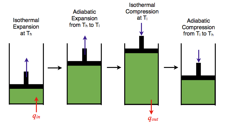
The Carnot cycle consists of the following four processes:
- A reversible isothermal gas expansion process. In this process, the ideal gas in the system absorbs \(q_{in}\) amount heat from a heat source at a high temperature \(T_{high}\), expands and does work on surroundings.
- A reversible adiabatic gas expansion process. In this process, the system is thermally insulated. The gas continues to expand and do work on surroundings, which causes the system to cool to a lower temperature, \(T_{low}\).
- A reversible isothermal gas compression process. In this process, surroundings do work to the gas at \(T_{low}\), and causes a loss of heat, \(q_{out}\).
- A reversible adiabatic gas compression process. In this process, the system is thermally insulated. Surroundings continue to do work to the gas, which causes the temperature to rise back to \(T_{high}\).
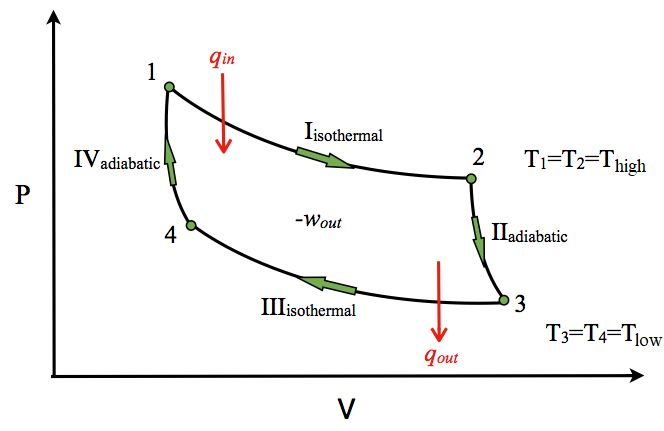
P-V Diagram
The P-V diagram of the Carnot cycle is shown in Figure \(\PageIndex{2}\). In isothermal processes I and III, ∆U=0 because ∆T=0. In adiabatic processes II and IV, q=0. Work, heat, ∆U, and ∆H of each process in the Carnot cycle are summarized in Table \(\PageIndex{1}\).
| Process | w | q | ΔU | ΔH |
|---|---|---|---|---|
| I | \(-nRT_{high}\ln\left(\dfrac{V_{2}}{V_{1}}\right)\) | \(nRT_{high}\ln\left(\dfrac{V_{2}}{V_{1}}\right)\) | 0 | 0 |
| II | \(n\bar{C_{v}}(T_{low}-T_{high})\) | 0 | \(n\bar{C_{v}}(T_{low}-T_{high})\) | \(n\bar{C_{p}}(T_{low}-T_{high})\) |
| III | \(-nRT_{low}\ln\left(\dfrac{V_{4}}{V_{3}}\right)\) | \(nRT_{low}\ln\left(\dfrac{V_{4}}{V_{3}}\right)\) | 0 | 0 |
| IV | \(n\bar{C_{v}}(T_{high}-T_{low})\) | 0 | \(n\bar{C_{v}}(T_{hight}-T_{low})\) | \(n\bar{C_{p}}(T_{high}-T_{low})\) |
| Full Cycle | \(-nRT_{high}\ln\left(\dfrac{V_{2}}{V_{1}}\right)-nRT_{low}\ln\left(\dfrac{V_{4}}{V_{3}}\right)\) | \(nRT_{high}\ln\left(\dfrac{V_{2}}{V_{1}}\right)+nRT_{low}\ln\left(\dfrac{V_{4}}{V_{3}}\right)\) | 0 | 0 |
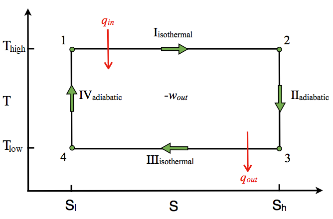
T-S Diagram
The T-S diagram of the Carnot cycle is shown in Figure \(\PageIndex{3}\). In isothermal processes I and III, ∆T=0. In adiabatic processes II and IV, ∆S=0 because dq=0. ∆T and ∆S of each process in the Carnot cycle are shown in Table \(\PageIndex{2}\).
| Process | ΔT | ΔS |
|---|---|---|
| I | 0 | \(-nR\ln\left(\dfrac{V_{2}}{V_{1}}\right)\) |
| II | \(T_{low}-T_{high}\) | 0 |
| III | 0 | \(-nR\ln\left(\dfrac{V_{4}}{V_{3}}\right)\) |
| IV | \(T_{high}-T_{low}\) | 0 |
| Full Cycle | 0 | 0 |
Efficiency
The Carnot cycle is the most efficient engine possible based on the assumption of the absence of incidental wasteful processes such as friction, and the assumption of no conduction of heat between different parts of the engine at different temperatures. The efficiency of the carnot engine is defined as the ratio of the energy output to the energy input.
\[\begin{align*} \text{efficiency} &=\dfrac{\text{net work done by heat engine}}{\text{heat absorbed by heat engine}} =\dfrac{-w_{sys}}{q_{high}} \\[4pt] &=\dfrac{nRT_{high}\ln\left(\dfrac{V_{2}}{V_{1}}\right)+nRT_{low}\ln \left(\dfrac{V_{4}}{V_{3}}\right)}{nRT_{high}\ln\left(\dfrac{V_{2}}{V_{1}}\right)} \end{align*}\]
Since processes II (2-3) and IV (4-1) are adiabatic,
\[\left(\dfrac{T_{2}}{T_{3}}\right)^{C_{V}/R}=\dfrac{V_{3}}{V_{2}}\]
and
\[\left(\dfrac{T_{1}}{T_{4}}\right)^{C_{V}/R}=\dfrac{V_{4}}{V_{1}}\]
And since T1 = T2 and T3 = T4,
\[\dfrac{V_{3}}{V_{4}}=\dfrac{V_{2}}{V_{1}}\]
Therefore,
\[\text{efficiency}=\dfrac{nRT_{high}\ln\left(\dfrac{V_{2}}{V_{1}}\right)-nRT_{low}\ln\left(\dfrac{V_{2}}{V_{1}}\right)}{nRT_{high}\ln\left(\dfrac{V_{2}}{V_{1}}\right)}\]
\[\boxed{\text{efficiency}=\dfrac{T_{high}-T_{low}}{T_{high}}}\]
Summary
The Carnot cycle has the greatest efficiency possible of an engine (although other cycles have the same efficiency) based on the assumption of the absence of incidental wasteful processes such as friction, and the assumption of no conduction of heat between different parts of the engine at different temperatures.
Problems
- You are now operating a Carnot engine at 40% efficiency, which exhausts heat into a heat sink at 298 K. If you want to increase the efficiency of the engine to 65%, to what temperature would you have to raise the heat reservoir?
- A Carnot engine absorbed 1.0 kJ of heat at 300 K, and exhausted 400 J of heat at the end of the cycle. What is the temperature at the end of the cycle?
- An indoor heater operating on the Carnot cycle is warming the house up at a rate of 30 kJ/s to maintain the indoor temperature at 72 ºF. What is the power operating the heater if the outdoor temperature is 30 ºF?
References
- Goldstein, M. J. Chem. Educ., 1980, 57, 114-116
- Bader, M. J. Chem. Educ., 1973, 50, 834
- W. F. Luder. J. Chem. Educ., 1944, 21, 600-601
- Salter, C. J. Chem. Educ., 2000, 77, 1027-1030